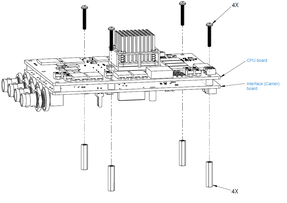
Setup - Two-Board Kit (Haivison P/N 084M090-501G)
Connect the CPU and Interface (Carrier) boards, using four (4) screws and standoffs (provided).
Connect the encoder's Network 1 port (Interface (Carrier) board J7) to the IP network (10/100/1000 network switch, with or without DHCP) using the Ethernet cable (p/n #084H074-614G). (Network 2 is reserved for future use.) See Ethernet Cable.
Note
The following picture shows the bottom side of the interface (Carrier) board.
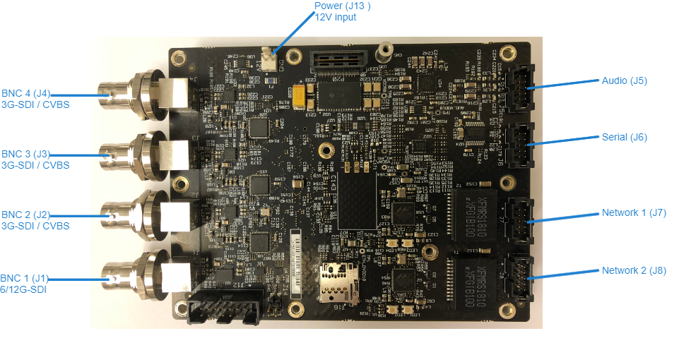
Connect the encoder’s Serial port (Interface (Carrier) board J6) to the metadata source or to the serial port of a computer using the serial breakout cable (p/n #084H074-612G). See Serial Cable.
You also need to connect the serial breakout cable to access the Reset button.
Note
Analog audio (Interface (Carrier) board J5) is reserved for future use.
Connect one or more of the encoder's Video ports to your video source(s) using the BNC connector(s).
Note
Only BNC1 can support input up to 6/12G-SDI. All the other inputs support up to 3G-SDI.
The CVBS ports are used to support legacy Analog NTSC/PAL/PAL-M cameras.
Connect the heat sink. See Attaching and Detaching the Heat Sink.
Connect the 12V power cable assembly (p/n #084H074-609G) to Interface (Carrier) board J13. See Power Cable - Two-Board Kit.
Apply +12V power.
The encoder will begin its booting sequence. If the serial port is connected to a PC, you can watch the boot sequence.
Related Topics