Serial Cable
The serial interface provides four (4) serial signals and one serial ground. The serial port supports RS-232 and RS-422 operation.
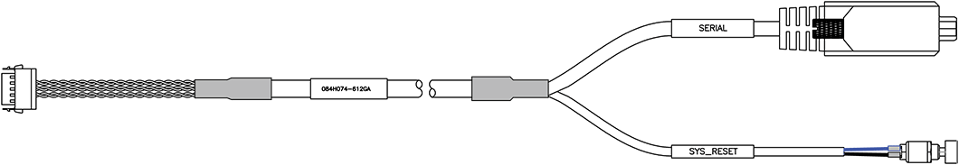
Serial Cable Assembly
(Haivision p/n #084H074-612G) This cable is used for both Assembly Kit Options. Use this cable to connect the encoder’s Serial port (Interface (Carrier) board J6) to the metadata source or to the serial port of a computer.
Serial Connector
Following is the breakout cable pinout for the Serial RS-232/422 and Reset signals.
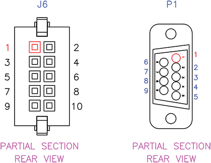
Serial Cable Pin Locations
Serial Connector (J6) Pinout | ||
|---|---|---|
Description | ||
Contact # | RS-232 | RS-422 |
1 | COM1 RX+ | COM1 RX+ |
2 | - | COM1 RX- |
3 | - | COM1 TX- |
4 | COM1 TX+ | COM1 TX+ |
5 | N/C | |
6 | N/C | |
7 | COM1 GND | |
8 | COM1 GND | |
9 | FACT RST # | |
10 | FACT RST GND | |
Serial Connector (J6) | ||
|---|---|---|
On Unit | Mating Connector | |
Manufacturer | SAMTEC | SAMTEC |
Connector Type | Serial Connector | Serial Connector |
Part Number | T2M-105-01-L-D-TH-WT | ISD2-05-D-M |
Serial Wiring Diagram
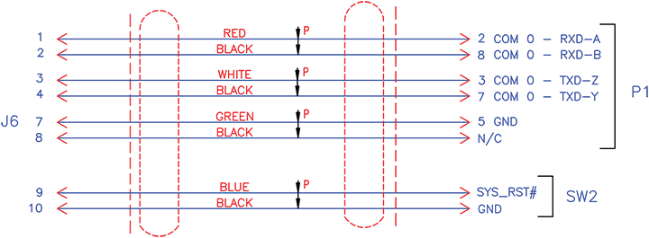
Serial Wiring Diagram
Resetting the Encoder Module
The Reset button is used either to reset the encoder module or to restore the factory default settings.
Pressing less than 5 seconds is a reset.
If pressed for more than 5 seconds, the encoder module will restore its factory configuration and erase all previously saved configurations. The default configuration is:
DHCP Disabled, Static IP: 10.5.1.2Gateway: 10.5.0.1, Netmask: 255.255.0.0
SERIAL:
SPEED : 115 200
DATABIT : 8
STOPBIT : 1
NO PARITY
NO HARDWARE FLOW CONTROL
NO LED CONTROL
RJ45 CONNECTOR
ETH0
10/100/1000 MBITS
RJ45 CONNECTOR
Setting the Terminal Parameters
To get started, you must set the terminal parameters to communicate with the encoder module.
To set up the serial interface:
Connect the encoder module’s Serial port (Interface (Carrier) board J6) to your computer as described in Assembling the Integrator's Board.
Power up the computer and start the serial communication application.
Set up the terminal parameters as follows:
Parameter | Setting |
|---|---|
Baud Rate/Speed | 115,200 bps |
Data Bits | 8 |
Parity | None |
Stop Bits | 1 |
Hardware Flow Control | None |
LED Control | None |
Power up the encoder as described in Assembling the Integrator's Board.
From the serial communication application, press Enter to get a prompt from the encoder.
It takes approximately two minutes for the encoder to boot. The system will request a login, or display the shell prompt if an active session is still running.
Tip
You can view the COM port settings from the Web interface. For information, see Managing the COM Port in the Makito X4 User's Guide.
We recommend that you log out from the encoder and exit from the serial communication application before disconnecting the Serial port.