Attaching and Detaching the Heat Sink
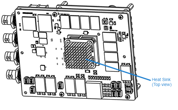
A heat sink (Haivision p/n 084K075-900G) is included in the assembly kit and must be installed on the FPGA of the CPU card assembly (as shown in the following figure, top view of the board assembly).
The kit includes the following items:
Heat sink assembly with springs for BGA (ball grid array)
Thermal pad
Heat sink removal tool
Attaching the Heat Sink
The heat sink kit is seated on the FPGA of the CPU card assembly.
To attach the heat sink:
Unpack the heat sink, thermal pad, and CPU card.
Remove the protective paper on both sides of the thermal pad.
Center the thermal pad onto heat sink.
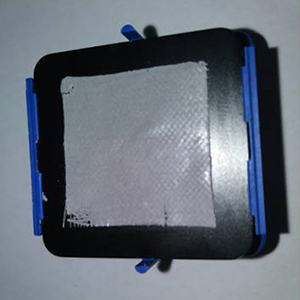
Thermal pad centered onto heat sink
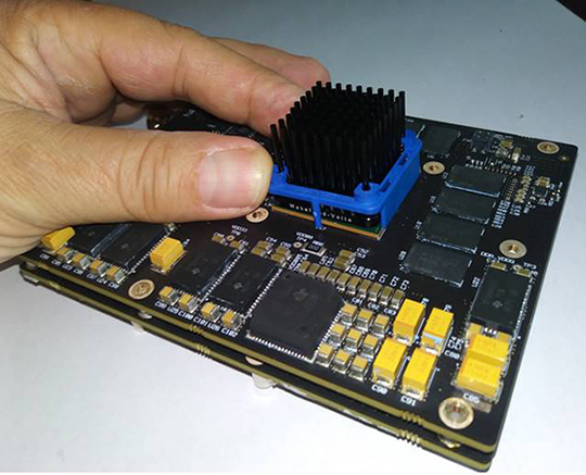
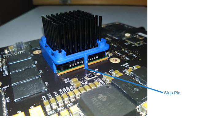
Center the heat sink onto the ball grid array (BGA) surface (on the FPGA of the CPU card).
Tilt and hook one side of the heat sink clip under the BGA chip.
Press down the other side of the heat sink clip to snap it onto the BGA chip.
Make sure the stop pin is not on top of the chip.
Installation is now complete.
Note
With 200 LFM (airflow speed) and at ambient temperature, the heat sink surface will go up to 67C°.
The heat sink fits perfectly on the FPGA, using four springs to apply adequate pressure on the thermal pad.
Detaching the Heat Sink
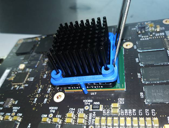
Slip the removal tool into the pry holes on the heat sink clip.
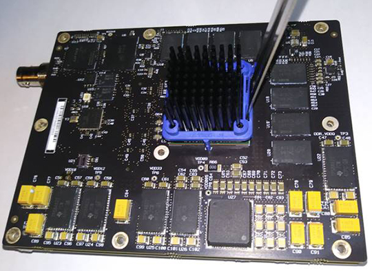
Slightly tilt the tool away from the heat sink to dislodge the clip.
Taking care not to damage the heat sink plates or pins, remove the loosened heat sink snap clip.
Note
The thermal pad may remain on the heat sink on the BGA chip.
Make sure not to damage the thermal pad.
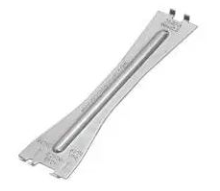
Heat Sink Removal Tool: