Powering Up the MB6
F-MB6X-RAC or F-MB6X-MED Chassis
To power up the F-MB6X-RAC or F-MB6X-MED Chassis:
Make sure the power switch(es) on the back of the chassis are in the OFF (2) position.
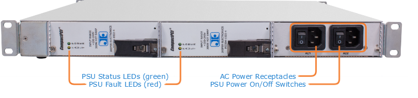
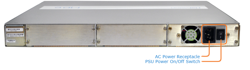
Connect the power cord(s) to one (or both) of the power receptacles shown in the figures above.
Note
The AC power cord shipped with the chassis is specific to the area (country).
Plug the cord(s) into a grounded AC power source.
Turn one (or both) PSU Power On/Off switches to the ON (1) position.
Wait until the Status LEDs stay solid green, indicating that the chassis is ready for operation.
F-MB6X-DC Chassis
To power up the F-MB6X-DC Chassis:
Make sure the power switch is in the OFF (2) position.
F-MB6X-DC Chassis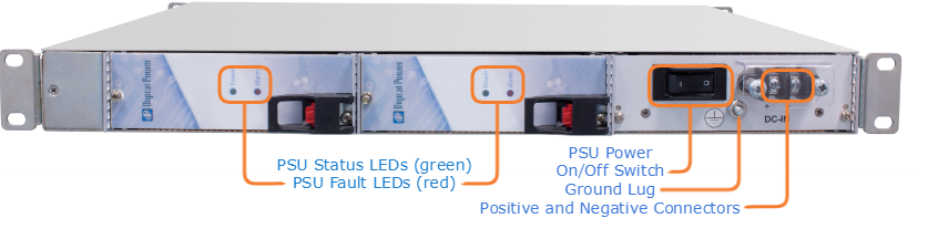
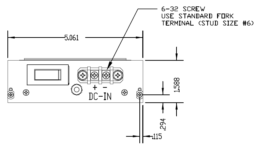
Locate DC Power IN connectors (+ and -) on the back of the chassis.
Connect the chassis ground wire to the ground lug on the back of the chassis.
Adhere to your organization's policy on the gauge of the ground wire (12 AWG, insulated, stranded) and the number of crimps on the lug.
Wrap each wire around the screw on the connector, and then tighten the screw firmly.
Note
Connect the screw marked + to a +28 VDC power source and the screw marked - to the neutral wire. The maximum width of the terminal lug is 0.32 inches (8.13 mm). The minimum wire gauge is 16 AWG.
F-MB6X-DC Chassis PDU Connections
Wait until the Status LEDs stay solid green, indicating that the chassis is ready for operation.
To begin configuring the unit, open the Web interface and sign in. Please refer to the encoder, decoder, or gateway product documentation for details.