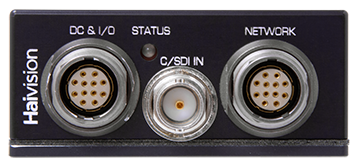
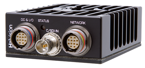
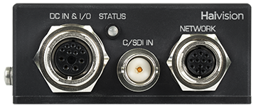
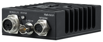
Enclosure Front Panel
Note
This page includes information regarding both the original Makito X1 chassis and the Makito X1 chassis v2. The Network connector and DC IN/IO connector on v2 have been changed in order to meet higher vibration requirements.
The Makito X1 Rugged enclosure provides rugged connectors for connecting the encoder's Power/Audio/Serial inputs, Video input, and Network interface, located on the front panel. There is one LED that indicates the power status.
| Makito X1 Rugged v2 (#S-MX1E-R-V2-SDI1) | Makito X1 Rugged (#S-MX1E-R-SDI1) |
|---|---|
|
|
Connectors
Connector | Description | Number of Contacts |
|---|---|---|
| DC IN and I/O Connector | Hirose P/N LF13WBRB – 11S | 11 |
| DC IN and I/O Connector v2 | Lemo P/N HEN.2M.312.XLNP | 12 |
| Video Input Connector | Coax BNC Jack Amphenol P/N 31-70551-12G | 1 |
Hirose P/N LF10WBRB – 12S | 12 | |
Lemo P/N HEP.2M.312.XLNP | 12 |
LED Status Indicator
Function | Description | Indication |
|---|---|---|
STATUS | Off | No power |
Green fast blinking | Reset button is pressed for less than four seconds. If the Reset button is not pressed, there is a power fault. | |
Green slow blinking | Booting/Initialization | |
Green solid | Booting/Initialization sequence is complete (No fault/OK). | |
Orange fast blinking | Reset button is pressed for more than five seconds (Factory Reset enabled). After Orange fast blinking, the LED turns off, stays off for a while, and then starts Green slow blinking towards the end of the booting up. |


