MB21 Installation
Note
The following installation steps apply to either MB21 model, unless specifically stated otherwise.
The MB21 may be installed in one of two ways: (1) free-standing on a desktop or rack shelf, or (2) fastened directly to a rack using support brackets (supplied).
Warning
To prevent electric shock, do not remove the cover of the MB21 chassis. There are no user-serviceable parts inside. The MB21 chassis is to be installed and serviced by qualified personnel only.
To install the MB21:
Unpack the box and visually inspect the package contents for any evidence of shipping damage. See the Important Notice document in the box for a list of contents.
In addition to the contents of the MB21 box, you may need to have the following items available:
5/16 hex nut driver
Screwdriver with Phillips #1 and #2 bits
Right-angle ratchet screwdriver or Allen key (for rack screws)
8 x rack screws
Place the MB21 on a solid surface.
Caution
The MB21 should always be moved or lifted by two persons. The handles on the front of the chassis should be used for a solid grip.
Using a 5/16 hex nut driver, remove the hex head screws – (E) and (F) in the figure below – holding the support brackets in place. Remove the support brackets.
If the MB21 is to be installed on a desktop or rack shelf, screw the rubber footpads into the base of the chassis. Move it to the desired location, and then skip ahead to Step #11. Otherwise, continue to the next step.
Position the empty MB21 in the rack at the desired location.
Tip
If space allows, put two screws into the rack posts just below the bottom of the MB21, and then rest the MB21 on those screws using the alignment notches at the bottom of the chassis mounting flanges. This will line up the screw holes on the MB21 flanges with the corresponding holes in the rack posts.
Using a right-angle ratchet screwdriver or Allen key, secure the front chassis mounting flanges to the rack (see red arrows in figure below; screws not provided).
Note
If necessary, you may remove the handles on the front of the chassis by using a Phillips #2 screwdriver to unscrew the four handle screws (see blue arrows in the following figure).
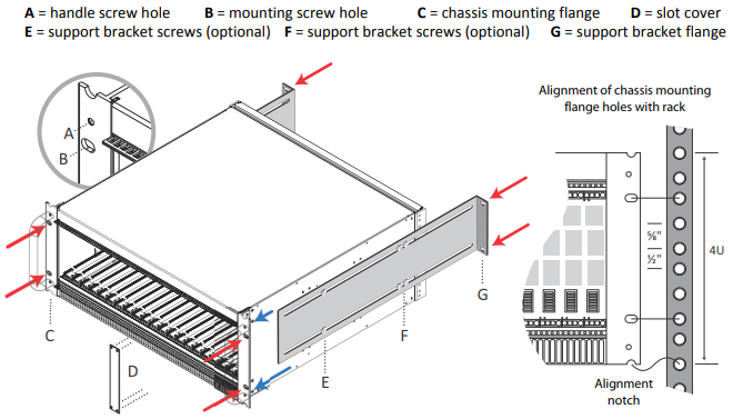
MB21 Chassis Installation
Loosely fasten the support brackets to the sides of the chassis with hex nut screws at (E) and (F). Slide them into place and secure them to the back of the rack (see red arrows in figure above; screws not provided).
Note
If you need to further extend the support brackets, you may safely remove the two screws at position (E) on each side.
Using a 5/16 hex nut driver, tighten the four screws at position (F) on each support bracket.
If needed, tighten the two screws at position (E) on each support bracket.
Using a Phillips #1 screwdriver, remove slot covers (D) as required.
Caution
Failure to properly secure or support the MB21 as described above may result in serious damage to the enclosure and/or its contents.
(F-MB21X-R only) If using a system interface, insert it now. The mating connector is provided but you will need to add your own wiring.
Insert the cards from the front (as shown in the figure on MB21 (21 Slot) Chassis.
Related Topics