Scenario 2: Internet streaming using Caller and Listener modes
In this scenario, an SRT source device (a Makito X Encoder in Caller mode) behind a firewall initiates a point-to-point session over the Internet with an SRT destination device (a Makito X Decoder in Listener mode), also behind a firewall.
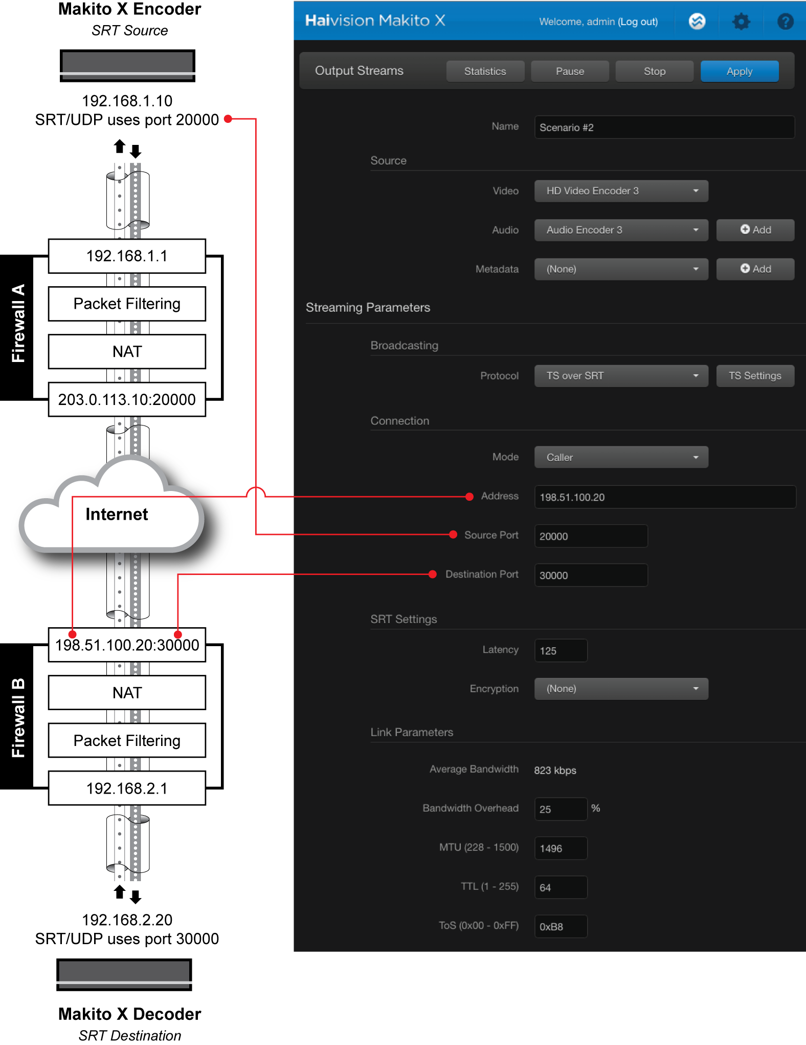
Step 1 – Configure the Makito X Encoder
On the Makito X Encoder (the SRT source device), do the following:
Using the settings in the table below, create and start an output stream:
| Setting | Example | Description |
|---|---|---|
| Protocol | TS over SRT | SRT is based on the UDP protocol. |
| Mode | Caller | Makito X Encoder will initiate the SRT connection. |
| Address | 198.51.100.20 | The target address for the SRT stream, which is the public IP address of Firewall B (at the destination). |
| Source Port | 20000 | The unique UDP source port for the SRT stream; you can leave the default value (Auto-assign), in which case an ephemeral port in the range of 32768 to 61000 is assigned, or, if required by your organization's IT policies, enter a specific (static) port number. If you use Auto-assign, then Firewall A must be configured to map ANY source port from its local side to a specific port on its public side so that return traffic can be directed to the Makito X Encoder. |
| Destination Port | 30000 | The port over which the Makito X Decoder will be listening. This is the publicly mapped port number for the SRT destination device (i.e. the port that Firewall B opens for the SRT session). This port must be known (it can't be "any"). |
Note
In the figure below, we are using the same port assignments (20000) for both Caller and its firewall to simplify the scenario. The Caller could, in fact, be using any other port, as long as its firewall had the appropriate mapping to allow return traffic back to the Makito X Encoder.
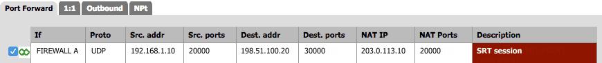
Step 2 – Configure the firewall at the source
On Firewall A (at the source), do the following:
Using the settings in the table below, create an outbound NAT rule that allows bidirectional UDP traffic, with a port forwarding entry for incoming traffic on the firewall's public IP address/port that forwards it to the Makito X Encoder's IP address/port number:
| Setting | Example | Description |
|---|---|---|
| Protocol | UDP | SRT is based on the UDP protocol. |
| Source IP | 192.168.1.10 | The Makito X Encoder's IP address. |
| Source Port | 20000 | In this case, we are using a static port assignment for the source port, but if auto-assigned it can be anything within the ephemeral port range (typically 32768 to 61000 on Linux devices). |
| Destination IP | 198.51.100.20 | This is the public IP address of Firewall B. |
| Destination Port | 30000 | This is the port over which the Makito X Decoder will be listening. |
| Outbound NAT Source Port | 20000 | Your firewall must support Outbound NAT Source Port (which disables NAT port rewrite). Otherwise, Rendezvous mode may be required (see Scenario #3). |
Here is an example of an outbound NAT rule for Firewall A:
Step 3 – Configure the firewall at the destination
On Firewall B (at the destination), do the following:
Using the settings in the table below, create an inbound NAT rule to enable forwarding of SRT traffic to the Makito X Decoder's IP address/port number:
| Setting | Example | Description |
|---|---|---|
| Protocol | UDP | SRT is based on the UDP protocol. |
| Source IP | 203.0.113.10 | This is the public IP address of the firewall at the source (Firewall A). |
| Source Port | 20000 | This must match the Outbound NAT Source Port on the firewall at the source (Firewall A). |
| Destination IP | 198.51.100.20 | This is the public (external) IP address of the firewall at the destination (Firewall B). |
| Destination Port | 30000 | This is the public (external) port of the firewall at the destination (Firewall B), which in this example is also the port over which the Makito X Decoder will be listening (dstport). |
| Redirect Target IP | 192.168.2.20 | This is the address of the Makito X Decoder (the internal destination IP). |
| Redirect Target Port | 30000 | This is the port over which the Makito X Decoder will be listening (the internal destination port, or dstport). |
Note
The Redirect Target IP and Port are the internal IP and port number that the destination device is using. Destination IP and Port are the firewall’s external interface. The port numbers don’t have to be the same. For clarity, it may be useful to always use the same port number, but this is up to your Firewall Administrator to decide.
Here is an example of an inbound NAT rule for Firewall B:

Using the settings in the table below, create a packet filtering rule to allow SRT packets to pass freely to and from the Makito X Decoder's IP address/port number:
| Setting | Example | Description |
|---|---|---|
| Protocol | UDP | SRT is based on the UDP protocol. |
| Source IP | 203.0.113.10 | This is the public IP address of the firewall at the source. |
| Source Port | 20000 | This must match the Outbound NAT Source Port on the firewall at the source. |
| Destination IP | 192.168.2.1 or 198.51.100.20 | Depending on your firewall, the NAT rules may be applied before or after the packet filtering rules. This will impact the filtering rule definition. If the NAT is applied before, you have to specify the Firewall B internal IP address. If the NAT is applied after, you have to specify the Firewall B public IP address. |
| Destination Port | 30000 | This is the port over which the Makito X Decoder will be listening (dstport). |
| Policy | Accept/Pass | Allows packets to pass freely between source and destination. |
Here is an example of a packet filtering rule for Firewall B:

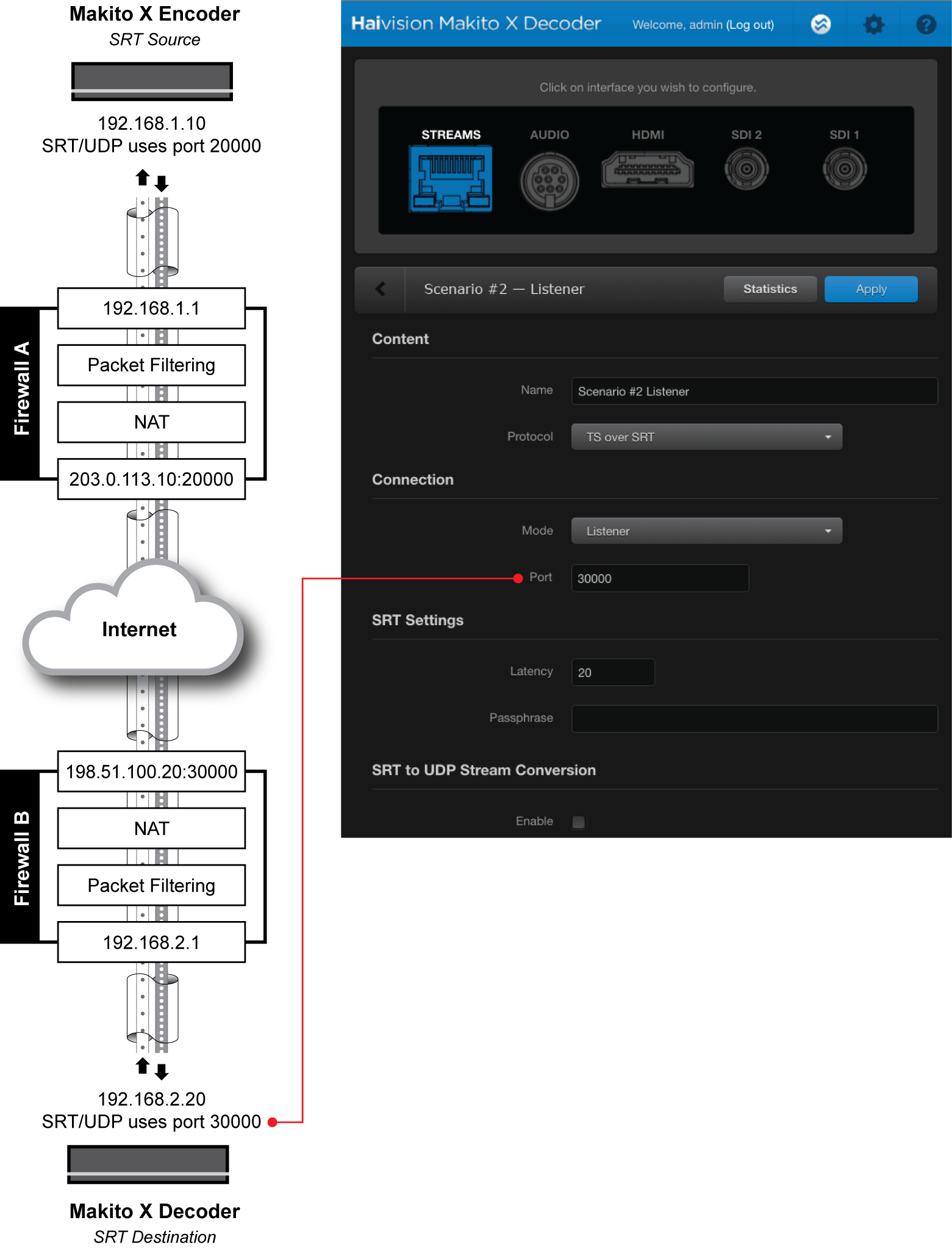
Step 4 – Configure the Makito X Decoder
On the Makito X Decoder (the SRT destination device), do the following:
Using the settings in the table below, create an Input Stream on the Makito X Decoder (the SRT destination device):
| Setting | Example | Description |
|---|---|---|
| Mode | Listener | The Makito X Decoder will wait for the source device to initiate the SRT session. |
| Destination Port | 30000 | This is the port on which the Makito X Decoder will be listening (the port to which Firewall B will be forwarding SRT packets). If you have a NAT translation rule on Firewall B, the Destination Port is the port to which the rule will be forwarding packets. |
Note
In the figure below, we are using the same port assignments (20000) for both Caller and its firewall to simplify the scenario. The Caller could, in fact, be using any other port, as long as its firewall had the appropriate mapping to allow return traffic back to the Makito X Encoder.
Once all settings have been applied, the Makito X Encoder and Decoder will handshake and establish an SRT session. The encoder will send the video stream to the decoder, which will process the stream and return control packets that include network throughput, latency and other statistics. The encoder can use this information to adapt its transmission (resend lost packets, adjust bit rate, etc.).
Note that when the SRT handshake is completed both source and destination continue to exchange control packets. Once an SRT connection/session is established, the Caller or Listener designation becomes unimportant. What matters is the source/destination relationship, or video flow, which is decoupled from the caller/listener relationship.