Connect to the Network and Audio/Video Sources
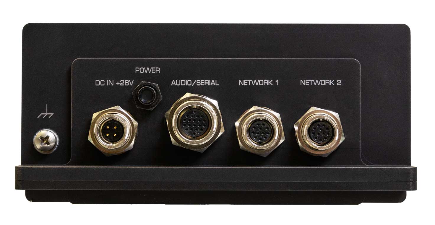
The Makito X4 Rugged enclosure provides rugged connectors for connecting the encoder's Network interface(s), as well as the Video, Audio, Serial, and Power inputs.
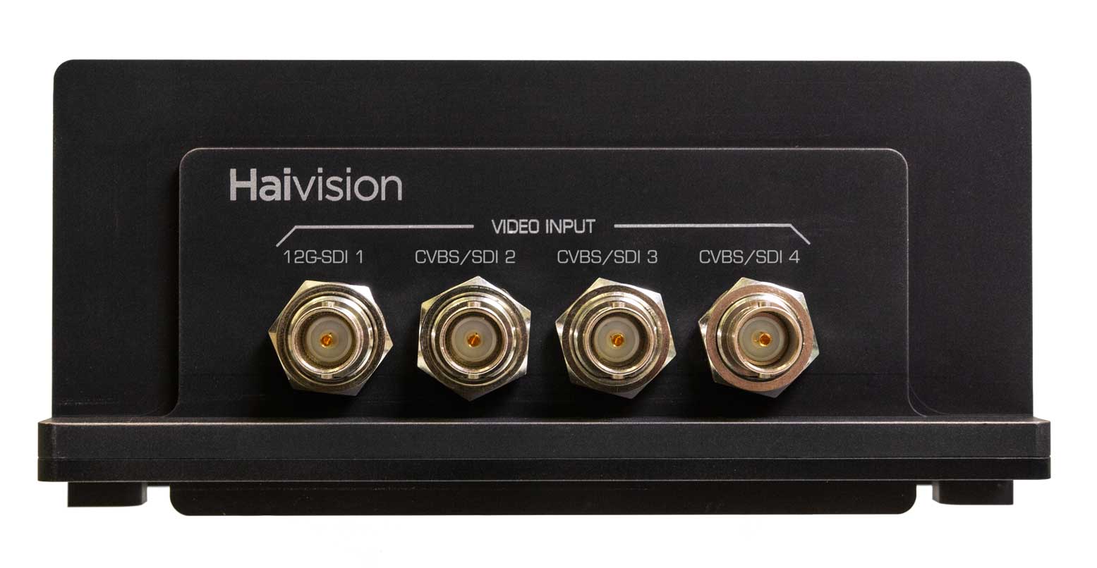
The Makito X4 Rugged encoder supports either one 12G-SDI 4K/UHD video input, or four 3G-SDI inputs, along with three or four analog composite CVBS (NTSC/PAL/PAL-M) inputs.*


Only SDI 1 can support input up to 6/12G-SDI video. All the other inputs support up to 3G-SDI.
*The number of CVBS inputs supported depends on the carrier type. You can confirm the carrier type information from the haiversion command or the Admin Status page (Status Settings). "Makito 4KR" indicates t he three-input variant , whereas "Makito 4KR 12G" indicates the four-input variant.
The Serial connector is used to ingest KLV/CoT, as a management port or as pass-thru for camera control.
As of Release 1.2, both Network 1 and Network 2 connectors are live.
The Ethernet and audio/serial breakout cables are shipped as part of the Evaluation Kit (#S-MX4E-R-SDI4-ISR-DK).
As of Release 1.4, the Makito X4 Rugged supports two (2) input channels of analog audio (via the Audio/Serial connector). To configure analog audio, see Set Up a Test Stream.
To connect the encoder to the network and A/V sources:
Remove the protective caps from the encoder's connectors.
Connect the encoder's Network 1 connector to the IP network using the Ethernet cable:
(Optional) To configure dual NICs for either streaming or management purposes, connect the encoder's Network 2 connector to the IP network.
Connect one or more of the encoder's Video connectors to your video source(s), referring to the above image (front panel, Video Input). The BNC connector(s) are used for SD-SDI (Serial Digital Interface), HD-SDI video, and Composite (CVBS) input signals. It is also a 3G-SDI capable interface supporting 1080p 50/60 fps video @ 3Gbps.
Note
The CVBS connectors are used to support legacy Analog NTSC/PAL/PAL-M cameras.
(Optional) If you have a KLV or CoT source that uses RS-232 or RS-422, connect the encoder’s Audio/Serial connector to the metadata source or to the serial port of a computer using the audio/serial breakout cable.
The Serial connector is used to ingest KLV/CoT, as a management port or as pass-thru for camera control.
Note
The Reset button provides two options:
If you press and hold the button for less than 4 seconds, the system resets and loads the last saved "startup" configuration. If no configuration was previously saved as the startup preset, the default settings prevail.
If you press and hold the button for more than 4 seconds, the module performs a complete factory reset. It clears all of the previously configured settings, including IP, streams and encoder configurations.
(Optional) To capture analog audio, connect the encoder’s Audio/Serial connector to your audio source(s) using the the audio/serial breakout cable, shown in the previous step.
Related Topics:


